| Emphasis on indoor air quality has dramatically affected HVAC system acoustical design. To obtain a healthier indoor environment, many duct systems today are designed without internal insulation. Ironically, the lack of insulation can actually decrease the indoor air quality with respect to a parameter that is often overlooked, indoor acoustics. Obtaining appropriate sound levels in an occupied space is one of many design considerations required to provide a healthy and comfortable indoor environment.
The following discussion outlines design guidelines that improve the indoor air quality from an acoustical perspective. This specifically addresses variable air volume terminals; however, many of the following guidelines can be applied to other HVAC equipment such as air handling and fan coil units. This discussion is based on the premise that internal insulation is not utilized in the air duct system.
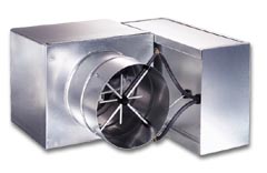
The discharge of the ENVIRO-TEC single duct terminal (Model SDR) has a slip-and-drive downstream duct connection providing a quiet, smooth transition. Foil insulation cut edges are taped with 2" foil tape encapsulating all fiber. Water based adhesive and metal stick clips secure insulation to the unit interior.
Air terminal units generate sound that propagates in two fashions commonly referred to as radiated sound and discharge sound. Radiated sound propagates from the sheet metal casing in all directions. With fan powered terminals, the sound emitted from the induction opening is also considered radiated sound. Discharge sound propagates from the air outlet of the terminal through the downstream air duct.
Sound is introduced into an occupied space along two primary paths. Radiated sound from the equipment travels through the ceiling cavity and enters the space below through the ceiling structure. Discharge sound travels through the downstream duct system and ultimately enters the occupied space through the room air outlet.
With fan powered terminals, radiated sound has always been the major design concern. Discharge sound for both fan and non-fan powered terminals was attenuated by the lined downstream duct before entering the occupied space. With the omission of internal duct liner, discharge sound now plays a more significant role in all VAV terminal applications. This discussion will be limited to discharge sound levels. A subsequent newsletter will address radiated sound concerns.
To reduce the amount of sound entering an occupied space served by an air terminal, the obvious starting point is to specify quiet equipment. Not all VAV terminals are created equal. A quick comparison of acoustical performance between AHRI certified products will help the designer narrow the choice of acceptable manufacturers. With single duct terminals, particular attention should be given to a comparison of discharge sound power levels. Many manufacturers’ terminals generate high discharge sound levels because of the obstructive airflow sensor that is employed.
Comparing NC levels will not be helpful since each manufacturer uses different attenuation factors to create NC levels. The only useful comparison to make is between raw sound power levels obtained in accordance with ARI Standard 880.
Although sound levels are published for a wide range of frequencies, space NC or RC levels are controlled by the lower frequencies of a VAV terminal. Generally, the space sound level will be controlled among the 125, 250, and 500 Hertz frequencies and most often will be dictated by the first two frequencies. This simplifies the comparison process as the higher frequencies are irrelevant. The following discussion will be focused on these lower frequencies.
Single duct terminals are available with a sound attenuator section that reduces discharge sound levels by 3 to 5 dB. Many projects require the terminal unit to utilize foil faced insulation in place of standard insulation. Surprisingly, foil facing only increases the discharge sound levels by 0 to 2 dB in the relevant frequency range. Foil liner is acoustically superior to the alternatives, no insulation and double wall construction. In these cases, the discharge sound levels increase as much as 7 dB over lined terminals depending on the product configuration.
One final acoustical consideration relevant only to single duct terminals is hot water coils. Often the coil is located immediately after the VAV air valve. On sound sensitive projects it is best to specify that the hot water coil be mounted downstream of a factory supplied sound attenuator. The improved air pattern resulting from this configuration will reduce the discharge sound levels considerably. A hospital project, where often a VAV terminal serves a small hard patient room with little to no downstream duct, is well served by this arrangement.
Contrary to popular opinion, specifying a larger air valve will reduce the radiated and discharge sound levels generated by the valve by a few dB. This can be readily verified by comparing acoustical performance at the same CFM between two different size terminals. This technique is not appropriate for all applications as it increases the minimum controllable CFM for variable volume operation. It is least effective in series flow (constant volume) fan powered terminals where the air valve has less impact on the overall sound levels generated by the terminal. Dual duct terminal applications would not benefit from a larger air valve since most often one or both of the valves are required to control down to complete closure. This technique is well suited for single duct reheat applications where the minimum CFM is as high as 50% of the maximum CFM, and in constant air volume situations.
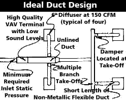
A major factor affecting acoustical performance of all types of air terminals is the static pressure at the primary air inlet. Often a system is designed for a much higher air terminal inlet static pressure than is required. Besides wasting energy, there is considerable acoustical penalty. Unnecessary sound is generated from the excessive static pressure as the air valve closes, increasing the differential static pressure across the valve. Series flow fan terminals can experience a modest decrease in sound levels by lowering the inlet static pressure. All other types of VAV terminals will experience a much greater reduction in sound levels resulting from lower inlet pressure. Approximately 3 dB can be saved by reducing the differential static pressure across the valve from 1.5" to 1.0" w.g. Up to 7 dB can be reduced by lowering the differential from 1.5" to 0.5" w.g. An ideal situation would exist with the inlet static pressure equal to that required to push the design airflow through the air terminal and downstream duct system. At this condition, the differential static pressure across the air valve would be minimized. Air terminals designed with extremely low air pressure drops can easily realize a reduction of 15 dB when operating at the minimum inlet static pressure instead of operating at 1.5" w.g. differential static pressure. Granted, it is impractical to design a system with all air terminals experiencing the minimum required inlet static pressure. However, to take advantage of the acoustical benefit, the supply duct system can and should be designed to minimize the static pressure variation among air terminals regardless of the proximity with the central air handler.
Lower air capacities generate lower sound levels. Designing smaller zones may be appropriate in critical applications.
Airborne sound is reduced by abrupt changes in direction. A reduction of 1 or 2 NC can be obtained by locating a diffuser takeoff after an elbow or tee duct fitting.
A significant decrease in discharge sound can be obtained by increasing the number of diffuser branches downstream of an air terminal. When sound traveling within a duct encounters a junction, the sound power is distributed between the branches. This is referred to as branch sound power division and is presented in detail in the ASHRAE HVAC Applications Handbook. Two branch ducts will decrease the sound level by 3 dB compared to a single duct with an area equal to the sum of the two smaller ducts. Ten equally sized branch ducts that collectively have the same area as the supply duct will decrease the discharge sound by 10 dB.
The additional branch ducts provide an additional acoustical benefit due to the smaller necked room outlets that will be utilized. When low frequency sound exists a small duct into a large room, a significant amount of the sound energy is reflected back into the duct. This phenomenon is referred to as duct end reflection loss and is also discussed in detail in the Applications Handbook. The absolute amount of sound reduction is dependent on a few variables of which the most important is the type of diffuser. Of importance, a 6" necked outlet will reduce the relevant sound levels by approximately 2 dB over an 8" neck and 3 or 4 dB over a 10" necked outlet.
Air balancing dampers should not be located at the room outlet but at the branch takeoff. In addition, non-metallic flexible duct should be connected to the room air outlet when local codes permit. Short pieces should be utilized to minimize potential bends that can increase air turbulence and pressure drop. A straight piece of flexible duct only 18" long can reduce the relevant frequency sound in the duct by 4 dB or more depending on the duct diameter and absolute level of sound. This significant reduction in discharge sound occurs due to the sound energy that breaks out of the flexible duct into the ceiling cavity just before it would have otherwise entered the occupied space through the outlet.
Acceptable sound levels can be obtained in an occupied space without the use of internal insulation downstream of an air terminal. The design guidelines presented above are by no means exhaustive. These guidelines are practical techniques that decrease discharge sound levels with a high benefit-to-cost ratio.
Top of Page |