
|
|
| Specifier's Guide Volume 5 |
Accurate Airflow Measuring With the FlowStar™ Sensor |
 HVAC designers today must consider both air quality code requirements spawned by ASHRAE Standard 62 (Ventilation for Acceptable Indoor Air Quality), and operating cost considerations. Variable air volume (VAV) systems are an effective solution for reducing both the first cost and operating costs for a building owner. Maintaining proper outside air dilution rates, air motion and air distribution becomes the challenge for the VAV system designer. HVAC designers today must consider both air quality code requirements spawned by ASHRAE Standard 62 (Ventilation for Acceptable Indoor Air Quality), and operating cost considerations. Variable air volume (VAV) systems are an effective solution for reducing both the first cost and operating costs for a building owner. Maintaining proper outside air dilution rates, air motion and air distribution becomes the challenge for the VAV system designer.
An airflow sensor in each VAV terminal measures the flow of conditioned air and sends a differential pressure signal to a controller. The accuracy and range of the airflow sensor and controller are critical to the system’s ability to control airflow, outside air dilution and air motion at part-load conditions. THE PROBLEM: Design For Part-load and Full-load ConditionsUntil recently, accurate airflow measurement at or near minimum airflow conditions was considered less important than thermal comfort. However, today maintaining proper minimum airflow setpoints is a primary concern to ensure proper ventilation in the occupied space. Even with sophisticated air diffusers, accurate airflow control is necessary to maintain proper air throws required for proper air diffusion within the space. HVAC system designers select VAV terminals for minimum pressure drop and noise, which often results in oversized terminals. These minimum design airflows can result in differential pressure signals below the range of control for VAV controllers. One of the following two problems results:
Undersizing VAV terminals to accommodate typical airflow sensors results in higher pressure drops and sound levels, increased energy consumption and noise in the occupied space. Conventional Airflow Sensors Cause Problems
THE SOLUTION: Accurate Airflow Measurement Permits Proper Ventilation and Stable Temperature ControlSuccessful VAV systems demand airflow measuring sensors that can accomplish the following:
 Airflow sensors should traverse the inlet duct using methods outlined in the ASHRAE Fundamentals Guide. Pressure measurements should be taken in equal cross sectional areas, or by using the log-linear traverse method along two perpendicular diameters (Figure 1). The number of pressure measurements should increase with the inlet collar size and be no fewer than six measurements per diameter (12 total sensing points). Airflow sensors should traverse the inlet duct using methods outlined in the ASHRAE Fundamentals Guide. Pressure measurements should be taken in equal cross sectional areas, or by using the log-linear traverse method along two perpendicular diameters (Figure 1). The number of pressure measurements should increase with the inlet collar size and be no fewer than six measurements per diameter (12 total sensing points).
Center Averaging is the Key The airflow sensor must average all the discrete pressure measurements instantaneously in a pressure collecting chamber located in the center of the sensor (Figure 2). Low velocity pressure on one side of the duct and high velocity pressure on the opposite side is averaged together in the center pressure collecting chamber before being output to the controller. Center averaging is the single most important characteristic required for accurate airflow measurement. Without this feature, the output pressure signal reflects the pressure measurement closest to the controller, rather than the average differential pressure within the duct. The airflow sensor must average all the discrete pressure measurements instantaneously in a pressure collecting chamber located in the center of the sensor (Figure 2). Low velocity pressure on one side of the duct and high velocity pressure on the opposite side is averaged together in the center pressure collecting chamber before being output to the controller. Center averaging is the single most important characteristic required for accurate airflow measurement. Without this feature, the output pressure signal reflects the pressure measurement closest to the controller, rather than the average differential pressure within the duct.
Amplifying the Airflow Sensor Signal Allows Lower Minimum Airflow SetpointsMany VAV controllers require a minimum differential pressure signal of 0.03 inch w.g. The airflow sensor should be able to generate this signal with only 400 to 450 FPM air velocity through the inlet collar. Conventional airflow sensors without amplification capabilities require approximately 700 FPM to generate a 0.03 inch w.g. signal. If 700 FPM represents a 20% minimum condition, the inlet velocity would be 3500 FPM at the maximum airflow setpoint. This results in extremely noisy conditions. In addition, the airflow sensor should generate a differential pressure range of at least one inch w.g. over the operating range of the terminal unit. Some Airflow Sensors Adversely Affect Noise and Air Pressure Drop
This method of amplification has the following negative side effects:
|
Sitemap | Terms of Use| Privacy| Terms and Conditions |
 Some airflow sensor designs amplify the velocity by enlarging the sensor face area (Figure 3). This method amplifies the velocity pressure in two ways:
 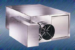 For maximum indoor comfort, specify CFRQ extra quiet fan powered terminals. This constant volume terminal provides higher air motion and better air distribution in the occupied space. The FlowStar airflow sensor permits adequate ventilation in the space. This combination provides the ultimate in zone comfort control.
 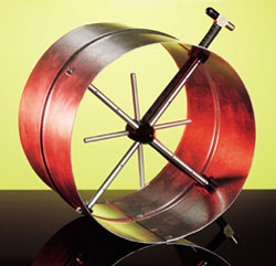 The FlowStar sensor is available as a stand alone airflow measuring station. The Model RFT-MS (right) is a short circular sheet metal sleeve that can be easily attached to any VAV terminal that has a round inlet. The old sensor can be removed and the FlowStar then connected to the existing controller.